- 描述
- Size Guide
- 評價 (0)
描述
描述
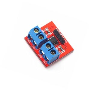
Arduino MAX471 電壓電流檢測模組 可同時感測電壓與電流
Arduino MAX471 電壓電流檢測模組 可以測量電路中的電壓、電流大小。電流檢測採用美國美信公司生產的精密高端電流檢測放大器晶片 MAX471。該模塊無需外接電源,模塊內部直接使用被檢測電源供電。MAX471工作電流最小為3V,所本模塊檢測的最小電壓輸入為3V。電壓檢測使用電阻分壓原理所設計, Arduino MAX471 電壓電流檢測模組 能使端子接口輸入的電壓縮小5倍。Arduino模擬輸入電壓最大為5V,那麼電壓檢測模塊的輸入電壓則不能大於5V×5=25V(如果用到3.3V系統,輸入電壓不能大於3.3Vx5=16.5V)
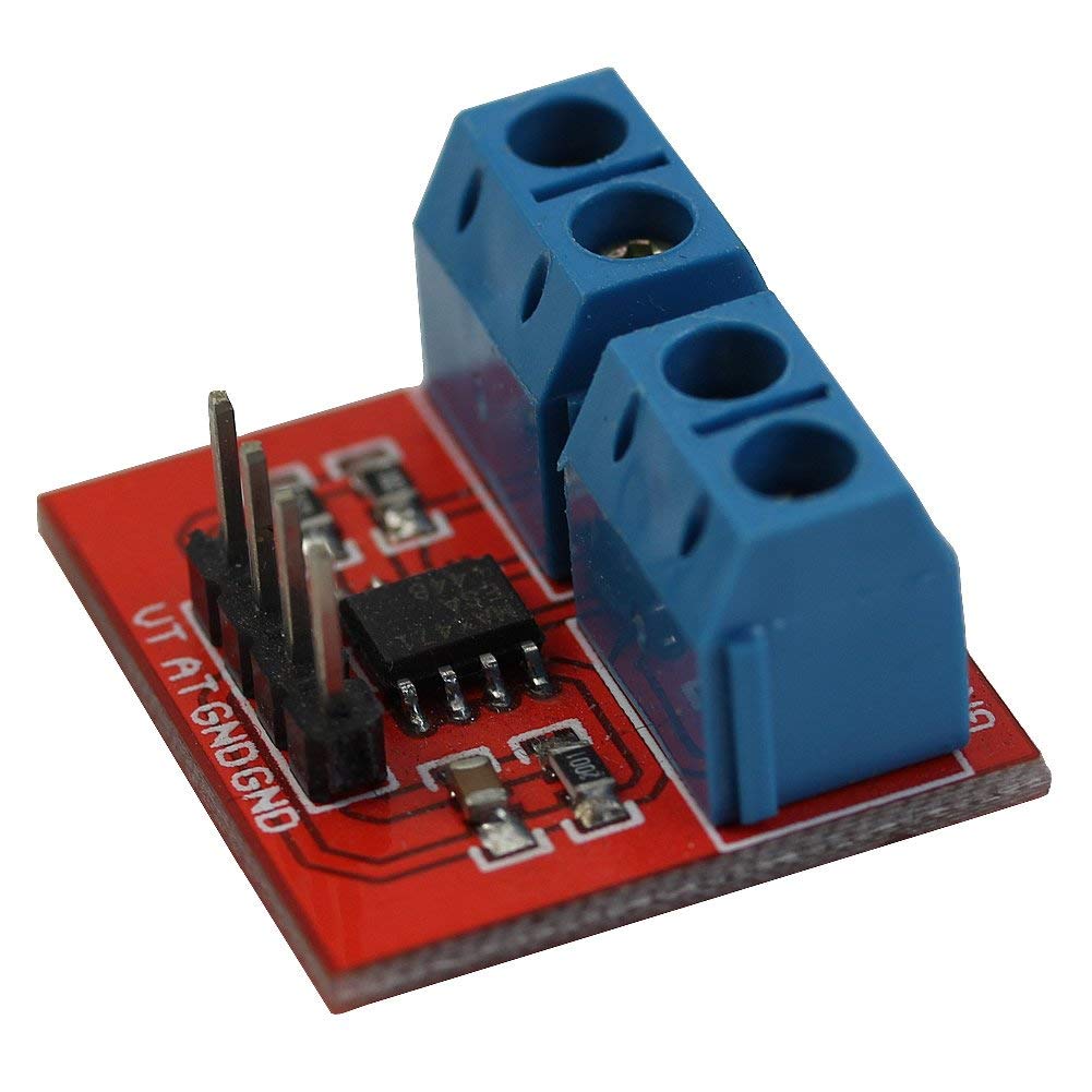
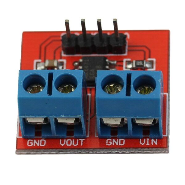
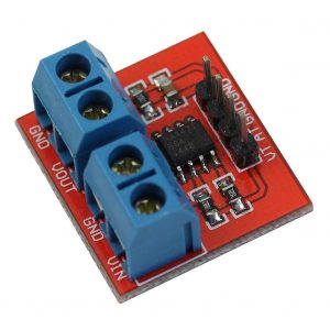
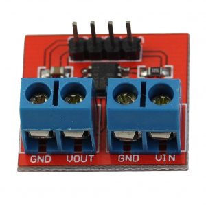
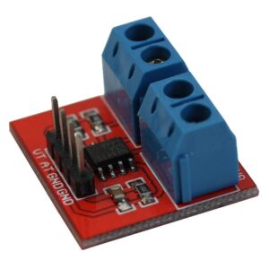
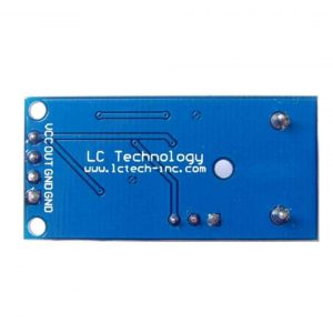
Arduino MAX471 電壓電流檢測模組 檢測引腳說明:
- VT: 電壓檢測引腳,檢測的電壓是輸入電壓的1/5
- AT:電流檢測引腳
- GND:接Arduino GND
- VOUT/VIN: VOUT=VIN
|
1 2 3 4 5 6 7 8 9 10 11 12 13 14 15 16 17 18 19 20 21 22 23 24 25 26 27 28 29 30 31 32 33 34 35 36 37 |
// Arduino code is available to download - link below the video /* Connection pins: Arduino Current Sensor B43 A0 VT A1 AT +5V VIN +5V VOUT GND GND */ #include <Wire.h> #define VT_PIN A0 // connect VT #define AT_PIN A1// connect AT #define ARDUINO_WORK_VOLTAGE 5.0 void setup() { Serial.begin(9600); Serial.println("Voltage (V) / Current (A)"); } void loop() { int vt_temp = analogRead(VT_PIN); int at_temp = analogRead(AT_PIN); double voltage = vt_temp * (ARDUINO_WORK_VOLTAGE / 1023.0) * 5; double current = at_temp * (ARDUINO_WORK_VOLTAGE / 1023.0); Serial.print("Analog0: "); Serial.print(vt_temp); Serial.print(" / "); Serial.print("Analog1: "); Serial.print(at_temp); Serial.print(" ----- "); Serial.print(voltage); Serial.print(" / "); Serial.println(current); delay(1000); } |
Arduino MaX471 Voltage & Current Sensor Module
- This module can be used to test the current and voltage
- The principle of voltage test based on principle of resistive voltage divider design, can make the red terminal connector input voltage to 5 times smaller
- Arduino analog input voltages up to 5 v, the voltage detection module input voltage not greater than 5Vx5=25V (if using 3.3V systems, input voltage not greater than 3.3Vx5=16.5V). Arduino AVR chips have 10-bit AD, so this module simulates a resolution of 0.00489V (5V/1023), so the minimum voltage of input voltage detection module is 0.00489Vx5=0.02445V
- The MAX471 chip on the board used to test the consume current of the load
- PCB Size: 22*21*7mm/0.86*0.82*0.27″”
This module can be used to test the current and voltage
The principle of voltage test based on principle of resistive voltage divider design, can make the red terminal connector input voltage to 5 times smaller
Arduino analog input voltages up to 5 v, the voltage detection module input voltage not greater than 5Vx5=25V (if using 3.3V systems, input voltage not greater than 3.3Vx5=16.5V). Arduino AVR chips have 10-bit AD, so this module simulates a resolution of 0.00489V (5V/1023), so the minimum voltage of input voltage detection module is 0.00489Vx5=0.02445V
The MAX471 chip on the board used to test the consume current of the load
Parameters:
Test Voltage range: DC3 – 25V (Arduino work on 5V) or DC3 – 16.5V (Arduino work on 3.3V)
Test Current range: DC0 – 3A
PCB Size: 22*21*7mm/0.86*0.82*0.27″”
Quantity:1pc
Package includes:
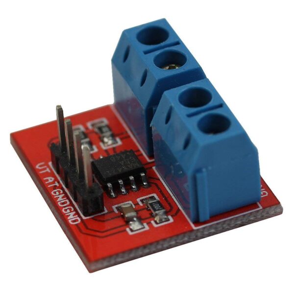
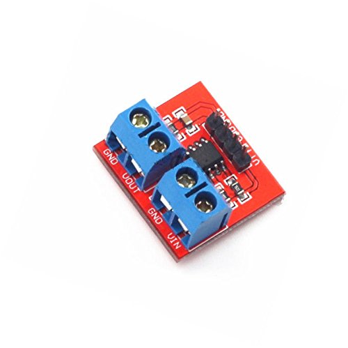
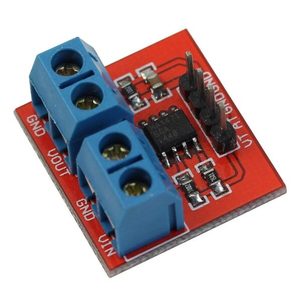
1 x Arduino Voltage And Current Sensor

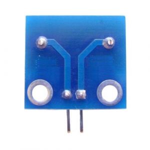
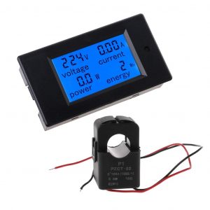
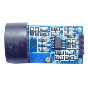
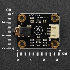
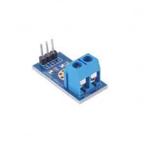

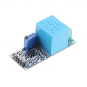
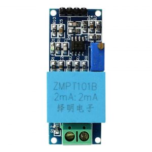
商品評價
目前沒有評價。