FREE Returns. Standard Shipping Orders $99+
Log In
Eng
Eng
Frh
USD
USD
EUR
Search
All Categories
小小創客
工具 & 控制組件
輸入控制單元
線材 & 配件 & 連接器
無線和物聯網
Robotics 機器人
智慧小車底盤套件
感測器 / 傳感模組
影像 / 成像 / 顏色 感測
紅外線科技
雜項未分類感測器
環境感測
壓力 / 彎曲 / 震動
液體 / 水質 感測
聲音傳感 / 音量感測
氣體感測
PM 2.5 空氣粉塵感測
溫濕度感測
光線 / 紫外線
氣壓 / 地磁 / 多功能 IMU
距離感測 / 接近感測
運動 / 位置 / 加速度
生物識別技術
電壓 / 電流
功能模組零配件
驅動模組/步進電機/馬達
按鍵 / 輸入 / 人機介面模組
LED / LCD / 液晶屏
無線通訊模組
RFID 無線射頻
ZigBee 無線模組
xbee 通訊模組
Lora 遠距低功耗模組
2.4G 無線模組
藍牙模組
WIFI 模組
繼電器模組
升壓/降壓/電源模組
衛星定位 GPS
其他功能模組
綠能應用開發模組
電磁鐵相關
DIY 套件與學習套件
開發平台與品牌
Arduino 開發板
聯發科 Linkit Smart
ESPRESSIF (ESP) 開發板
BBC Micro Bit 單板電腦
樹莓派 Raspberry Pi
香蕉派 Banana PI
其他類型開發板
NVIDIA 人工智慧開發平台
AI 人工智慧
SparkFun MicroMod 系列
Shield / 功能擴展板
Arduino 功能擴展板
工業物聯網 / 工控模組
ROCK Pi 單板電腦
未分類
MATTER 智慧家居
ESPHOME 零組件周邊
CALL US NOW
+123 5678 890
0
0
Special Offer!
Buy Porto!
NEW
JDY-40 2.4G 無線串口透傳收發一體遠距離通信模組 免開發超越 NRF-24L01
Home
Shop
功能模組零配件
,
無線通訊模組
,
2.4G 無線模組
JDY-40 2.4G 無線串口透傳收發一體遠距離通信模組 免開發超越 NRF-24L01
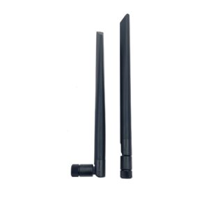
“2.4G 4db 內置 PCB天線 藍牙& wifi 天線模組 高增益全向天線 IPX接口”
has been added to your cart.
相關商品
-10%
加入購物車
Add to wishlist
Quick View
Add to wishlist
2.4G 無線模組
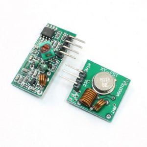
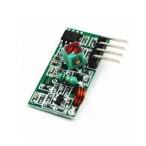
433MHZ RF 無線模組 Arduino 遙控器 433M 含發射與接收模組
0
out of 5
NT$
50
原始價格:NT$50。
NT$
45
目前價格:NT$45。
(未稅)
-6%
加入購物車
Add to wishlist
Quick View
Add to wishlist
ZigBee 無線模組
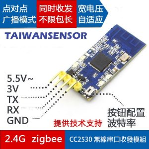
2.4G zigbee CC2530 無線串口收發模組 DL-20
0
out of 5
NT$
350
原始價格:NT$350。
NT$
330
目前價格:NT$330。
(未稅)
-29%
加入購物車
Add to wishlist
Quick View
Add to wishlist
ZigBee 無線模組
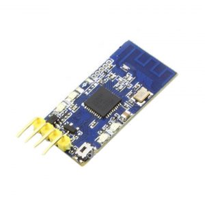
zigbee Ti CC2530 開發板模組串口 無線開發板 CC2530 核心板
0
out of 5
NT$
360
原始價格:NT$360。
NT$
255
目前價格:NT$255。
(未稅)
-14%
加入購物車
Add to wishlist
Quick View
Add to wishlist
2.4G 無線模組
2.4G 4db 內置 PCB天線 藍牙& wifi 天線模組 高增益全向天線 IPX接口
0
out of 5
NT$
35
原始價格:NT$35。
NT$
30
目前價格:NT$30。
(未稅)
-21%
加入購物車
Add to wishlist
Quick View
Add to wishlist
2.4G 無線模組
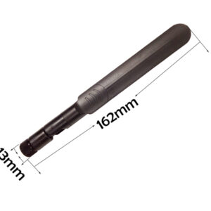
2.4G/5G/5.8G雙頻內針10dbi 全向高增益天線 WIFI/藍芽模組天線 SMA 接頭
0
out of 5
NT$
120
原始價格:NT$120。
NT$
95
目前價格:NT$95。
(未稅)
-19%
加入購物車
Add to wishlist
Quick View
Add to wishlist
2.4G 無線模組
2.4G/5G/5.8G雙頻內針 8dbi 全向高增益天線 WIFI/藍芽模組天線 SMA 接頭
0
out of 5
NT$
105
原始價格:NT$105。
NT$
85
目前價格:NT$85。
(未稅)
-24%
加入購物車
Add to wishlist
Quick View
Add to wishlist
2.4G 無線模組
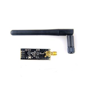
NORDIC原裝 NRF24L01+PA+LNA 含天線 2.4G 無線收發模組 加強型無線模組 1100米
0
out of 5
NT$
210
原始價格:NT$210。
NT$
160
目前價格:NT$160。
(未稅)
-23%
加入購物車
Add to wishlist
Quick View
Add to wishlist
2.4G 無線模組
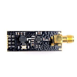
nRF24L01 USB 無線串口模組 串口轉 nRF24L01+ 無線通訊模組
0
out of 5
NT$
150
原始價格:NT$150。
NT$
115
目前價格:NT$115。
(未稅)
has been added to your cart.
查看購物車
結帳
All Categories
小小創客
工具 & 控制組件
輸入控制單元
線材 & 配件 & 連接器
無線和物聯網
Robotics 機器人
智慧小車底盤套件
感測器 / 傳感模組
影像 / 成像 / 顏色 感測
紅外線科技
雜項未分類感測器
環境感測
壓力 / 彎曲 / 震動
液體 / 水質 感測
聲音傳感 / 音量感測
氣體感測
PM 2.5 空氣粉塵感測
溫濕度感測
光線 / 紫外線
氣壓 / 地磁 / 多功能 IMU
距離感測 / 接近感測
運動 / 位置 / 加速度
生物識別技術
電壓 / 電流
功能模組零配件
驅動模組/步進電機/馬達
按鍵 / 輸入 / 人機介面模組
LED / LCD / 液晶屏
無線通訊模組
RFID 無線射頻
ZigBee 無線模組
xbee 通訊模組
Lora 遠距低功耗模組
2.4G 無線模組
藍牙模組
WIFI 模組
繼電器模組
升壓/降壓/電源模組
衛星定位 GPS
其他功能模組
綠能應用開發模組
電磁鐵相關
DIY 套件與學習套件
開發平台與品牌
Arduino 開發板
聯發科 Linkit Smart
ESPRESSIF (ESP) 開發板
BBC Micro Bit 單板電腦
樹莓派 Raspberry Pi
香蕉派 Banana PI
其他類型開發板
NVIDIA 人工智慧開發平台
AI 人工智慧
SparkFun MicroMod 系列
Shield / 功能擴展板
Arduino 功能擴展板
工業物聯網 / 工控模組
ROCK Pi 單板電腦
未分類
MATTER 智慧家居
ESPHOME 零組件周邊
Check the Main Menu location in
Apppearance->Menus->Display Location
.
Special Offer!
Buy Porto!
NEW